Project by: Amos Dotson (9th Grade)
Project Advisor: Kara Luce
Student(s)’s Advisor(s): Ashely Suan
Description of the Project: This project was focused on understanding the mechanics of cars by taking an approach where I learned about one section of the internal combustion engine every week.
Final Reflection on Learning: Throughout this project, I was able to finally understand how our cars operate. From watching youtube videos to getting hands-on experience, I learned more than I ever thought possible. I also came to the realization about myself as a student that at the end of studying something it is very helpful to take the time to express what I have learned in some form of writing.
Update on Progress from Weeks 1-3:
In the first two weeks of this project, I got a grasp on what I wanted to do during this time, and how I wanted to do it. I came up with a plan for my project where I would pick a topic each week to study and diagram. In the third week, I decided to focus on what turbocharging a car does to the engine.
Turbocharging
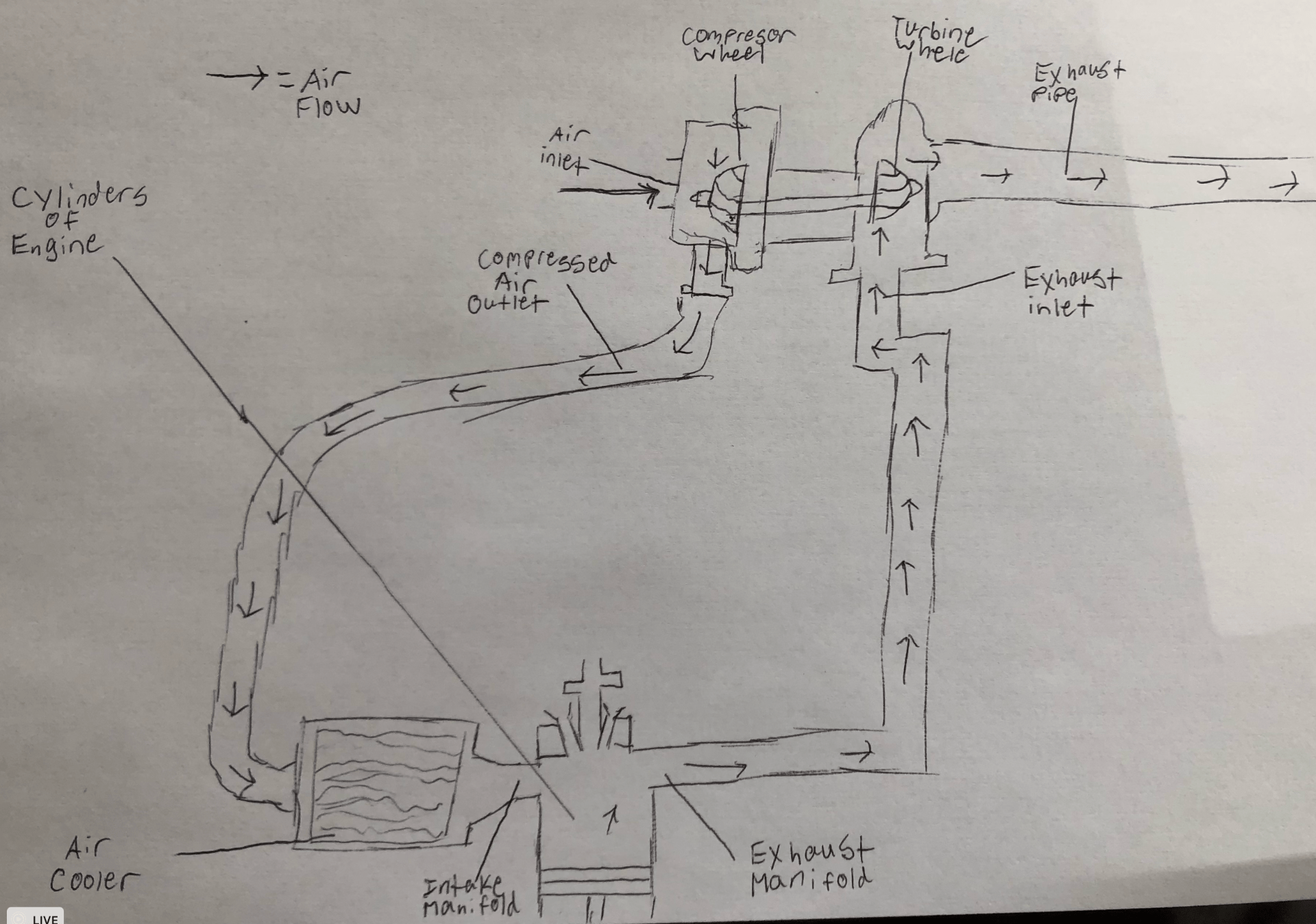
What is a turbo?
A turbo is a system that uses engine exhaust to suck more air and denser air into the engine to then go fire in the cylinders. It does this by having two wheels connected by a shaft that spins them in opposite directions. This means that as the exhaust pushes the turbine wheel, the compressor wheel spins with that force but sucking air in rather than pushing it out. The air being sucked in by the compressor wheel is denser than normal because of how strong the vacuum sucking it in is but it is still very hot. Hot air expands which makes it less dense which is not good because a turbo’s job is to densify air. Also, hot air can be bad for your engine. To solve this all of the air goes through an air cooler which makes it even denser before finally reaching the intake manifold and entering the engine.
Why do people want to turbo their engines?
People choose to turbo their car because it allows for more dense air in their engine which means more fuel can go into their engine. This is because there is a maximum fuel-to-air ratio that is safe for a combustion engine. When more fuel gets into the engine the faster the combustion process is, making your car even faster
Are there any drawbacks to turbos?
There is one large drawback to turbocharging an engine and it is that there is a lag between when the turbo comes in effect and when you start pushing on the pedal. This is because a turbo is fueled by exhaust and many cycles of combustion have to happen before that exhaust is there to spin the turbine wheel.
My diagram of a Turbocharger
Update on Progress from Weeks 4-6:
In weeks 4-6, I focused on three different topics. These were 4 Stroke Combustion, Carburetors, and Fuel Injection.
What is 4 Stroke Combustion?
I like to think of 4 Stroke Combustion as the source of power for a car engine. As the name suggests, there are four different phases to 4 Stroke Combustion that turn the fuel you put into your car into power and the exhaust that comes out.
Intake – Intake is the first of the four phases where the cylinder gets a mix of fuel and air. The air comes through the intake manifold and the fuel comes from a fuel injector that can be placed in many different areas(See Fuel Injector Section). In this phase, the piston is at the lowest point in the cylinder to maximize the amount of air/fuel that can be put in. During Intake the Intake manifold is open but the Exhaust Manifold is closed.
Compression – Compression is the second phase of combustion and its purpose is to make the air/fuel very compact. This is preparation for the next step, power. During the Compression phase, the piston is moving up in the cylinder to give the air/fuel, less space to move around. Both the Intake Manifold and Exhaust Manifold are closed during this phase.
Power/Explosion – This is the phase of combustion where power is created. That super dense air/fuel is ignited by a spark plug at the top of the piston creating an explosion. The explosion forces the piston downwards spinning the crankshaft which is converted to the wheels using the transmission. During this phase, the Intake Manifold and Exhaust Manifold are closed.
Exhaust – Exhaust is the last Phase of combustion in which all of the byproducts of combustion are pushed out of the cylinder through the Exhaust Manifold. In this phase the piston is moving up, forcing all of the exhaust out of the cylinder.

My Diagram of 4 Stroke Combustion
Fuel Injectors
Fuel Injectors’ jobs are to distribute fuel into the cylinder on every intake stroke. There are 2 common ways to do this on a gas engine and another common way on a diesel engine. Gas engines mainly use Port or Direct fuel injection. Diesel engines also have the option of using Indirect fuel injectors. Each of these different types of fuel injection has benefits and drawbacks but all get the job done.
Port Fuel Injection – Port Injection is most commonly used because it is cheap to manufacture and very reliable. It is cheap because the injectors are placed on the outside of the cylinder meaning that they don’t have to be able to withstand the pressure of the compression stage of combustion. For this reason, they are more reliable too. They are also very consistent because the fuel has a lot of time to mix with the air before entering the engine.
Direct Fuel Injection – There are two types of Direct Fuel Injection that operate on the same principles, Wall Guided, and Spray Guided. The difference is the placement of the injectors. Wall Guided have the injectors on the sides of the cylinder and spray sideways, Spray Guided injectors spray the fuel downward from the top of the cylinder. The big difference from these to Port Injection is that Direct fuel Injection sprays fuel straight into the cylinders rather than in the intake manifolds. These types of injection do use the same fuel injector mechanism as Port Fuel Injection but the injectors in Direct Fuel Injection have to be extra sealed off between intake strokes so that the injector is not damaged by the compression.
Indirect Fuel Injection – Indirect Fuel Injection is very abstract in its design compared to the others because the fuel isn’t technically sprayed into the cylinder. For Indirect Fuel Injection, air, after the compression stroke is finished, is pushed into a small pre-ignition chamber where it is combined with fuel and ignited by the spark plug. The explosion leaves the ignition chamber and goes back into the main cylinder to complete the power stroke. In this process, the fuel injector still needs to be very durable because it is injecting into the pre-ignition chamber.

My Diagram of Port, Direct, and Indirect Fuel Injectors
Carburetors
The Carburetor is a more old-fashioned way of getting fuel and air into the engine and was phased out by most auto manufacturers in the 1980s. Carburetors are their own chamber where they mix fuel and air that are quantified by a couple of different valves. At the very top of the chamber, there are air filters but right below that is the choke valve. The Choke Valve allows the perfect amount of air to flow into the venturi where it is mixed with fuel. The Throttle Valve controls how much air and fuel get into the cylinders when they fire. The float chamber is where small amounts of fuel are held before entering the venturi through the Jet. The level of fuel in the float chamber is controlled by the Float connected to a Float Arm which raises a valve blocking the fuel when the Float Arm lowers. Once the air/fuel is mixed it leaves the Carburetor for the cylinders.
Update on Progress from Weeks 7-9: In the final weeks of my project I studied the Exhaust System as well as the Transmission System of manual cars. Lastly, I completed my final project which was an install of a cold air intake.
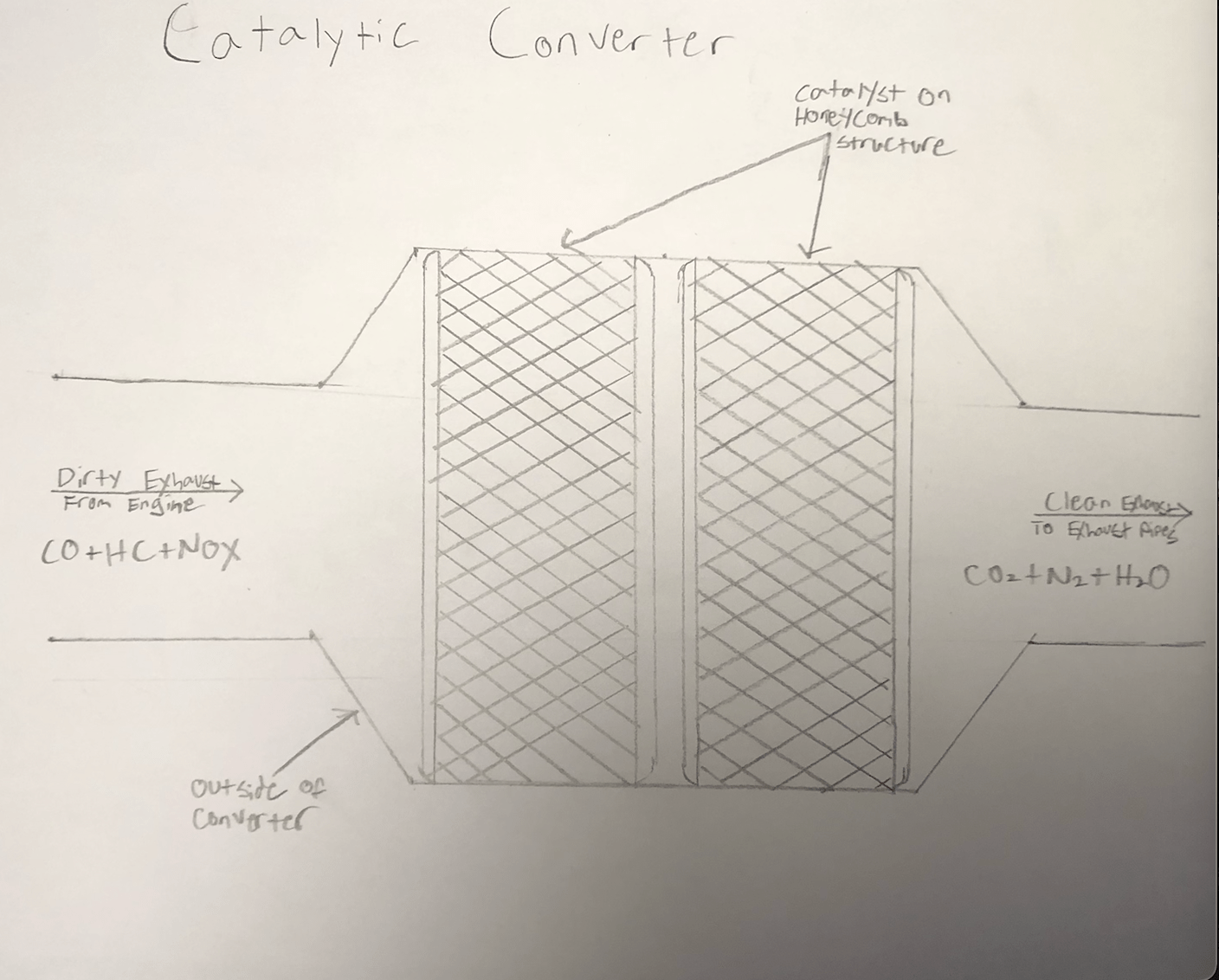
The Catalytic Converter: The Catalytic Converter is the core part of an exhaust system for a car. The Catalytic Converter’s purpose is to change the toxic exhaust that comes out of the engine into something less harmful. It does this by using heat and metals like Platinum, palladium, rhodium, copper, nickel, cerium, iron, and manganese. These metals are very valuable making Catalytic Converters a major target for thefts.
Mufflers: Mufflers are used as a way to mute the sound that comes from your car’s exhaust. They do this by having walls that break up sound waves while still allowing the air to flow out of the exhaust tips. Many people do what is called “straight piping” or a “muffler delete” when they get a car to make it sound faster and possibly gain a couple horsepower.
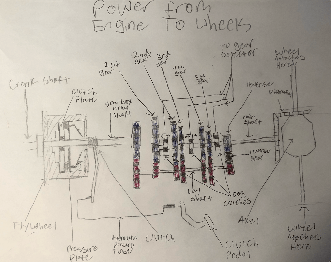
Transmission: The transmission is arguably the most complicated part of a car other than the engine. The transmission’s job is to turn the power created by 4 stroke combustion and make it possible for that power to spin your wheels. The gears of the car allow you to change speed without going to a crazy amount of RPMs. For example, a car might need to be going at 7000 RPMs to reach a specific speed 1st gear, 4500 RPMs to reach the same speed in 2nd gear, and 3000 RPMs to reach it in 3rd gear. In a manual car to switch gears, you press on the Clutch pedal which stops the Gearbox Input Shaft and the Fly Wheel from spinning. Once nothing past the Crankshaft is spinning you use the gear selector to pick which gear gets engaged by one of the Dog Clutches. If non of the Dog Clutches are engaged no power will be transmitted to the main shaft, this is when the car is in Neutral. When the main shaft is spinning it turns a gear in the differential which is facing perpendicular to the main shart. That gear engages with a gear parallel to the main shaft that spins the axel which is connected to the wheels. Lucky for mechanics, the future lies in electric cars which don’t have transmissions. Electric cars don’t have transmissions because they have a much higher RPM limit than combustion cars.
Final Product: Installation of Cold Air Intake
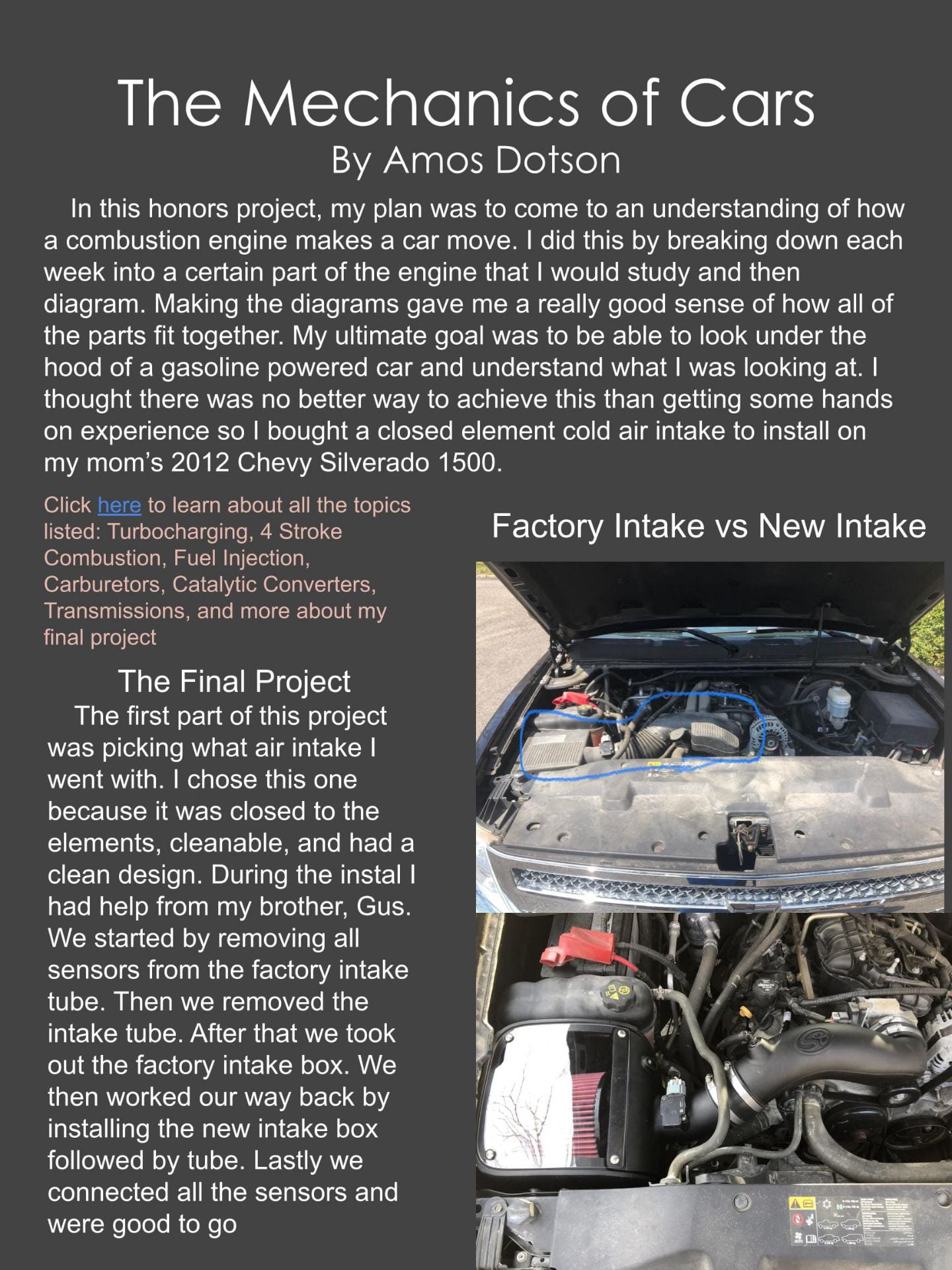
Finding the Correct Part for Me
Before starting to install the cold air intake I had to find the one that best suited my needs online. These needs were ease of installment(This was my first time working on a car engine), closed element, clean looking(but not too crazy looking because the vehicle I was installing it on was my mom’s), and good reliability. I found this filter browsing through youtube and it fit all of my criteria and even had an install tutorial which was perfect for me.
The Tools
Once I ordered it I needed to acquire all of the necessary tools which included, an impact wrench, small and large ratchet extensions, T-15 torque spit, small and large Phillips head screwdrivers, 8mm and 10mm sockets, and a swivel socket. Then I found out that my torque spit didn’t fit my impact wrench so I had to ask my brother to borrow his impact gun.
The Install
The install went completely smooth other than a couple parts that were sticky and stuck, but thanks to the help of my older brother we were able to get them out with minimal wrestling. We started by disconnecting the MAF sensor wire harness and breather tube from the intake tube. Next, we loosened the two band clamps that were holding the intake tube on. We ran into a bit of trouble after we removed the clamps because there was another bracket holding a hose to the intake tube even though they weren’t fully connected. As I undid the bracket my brother pulled the intake tube out of the engine bay. Taking this part out was a great feeling because it was the first moment where the engine bay looked very different. The last part of the disassembly was taking out the factory airbox along with its bracket. They came out easily enough but the bolts were very rusted in so instead of using the impact wrench we had to take them out manually using a rachet. Once everything was out I took the MAF sensor off of the factory intake tube using the T-15 torque spit and put it into the new intake tube using new hardware. The first part of the installation of the new cold air filter was the new airbox. This went in easily with four 10mm bold(2 new, 2 from factory). Then we connected the filter and the engine bay side of the airbox with a band clamp which was sealed to the rest of the airbox by the plexie glass cover. The plexie glass cover was a big reason why I got this specific cold air intake because it allows you to see when you need to service the filter. After the whole air intake was set up we installed the new intake tube using four band clamps to make sure that it was extra secure. Then lastly, we connected the MAF sensor and breather tube.
Results
I could not be happier with the results of this Cold Air Intake. The horsepower was bumped up 10-20 horsepower but the main benefit was the increase in throttle response. I think that the increase in throttle response and horsepower was better than expected because when we pulled off the factory intake box it looked like there had been mice living in there for a while. Most importantly, I learned more than I could have ever expected while doing this final project about where things are positioned under the hood, and how to use tools on your car.
Photos From the Install
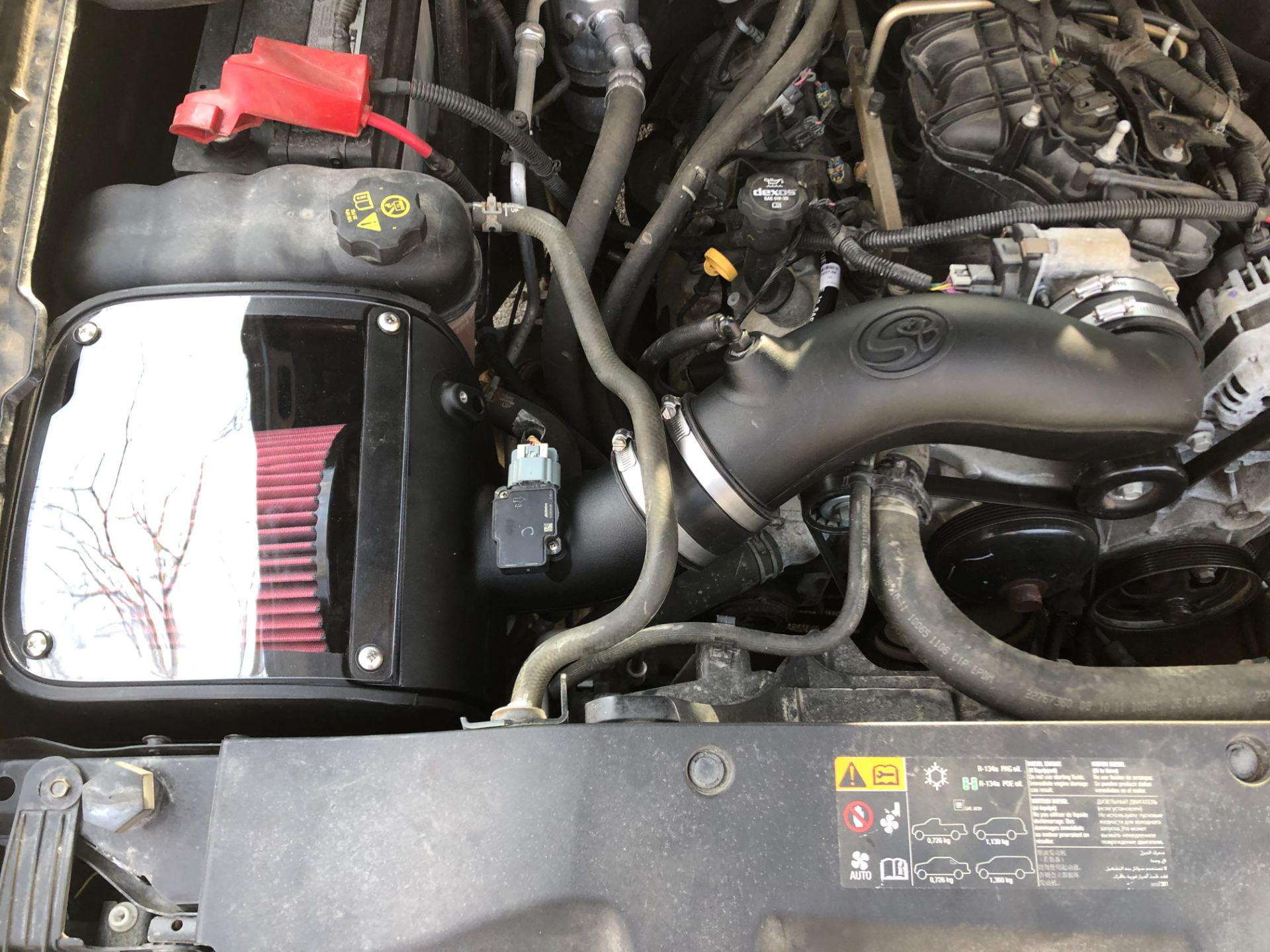
Brand New Cold Air Filter!!!

Factory Air Intake(Outlined in blue)
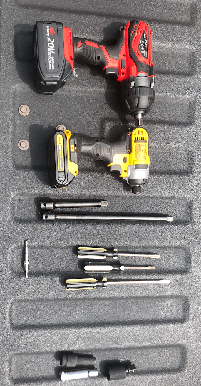
Tools Used on Install not Including Rachet

Breather Hose After Being Disconnected
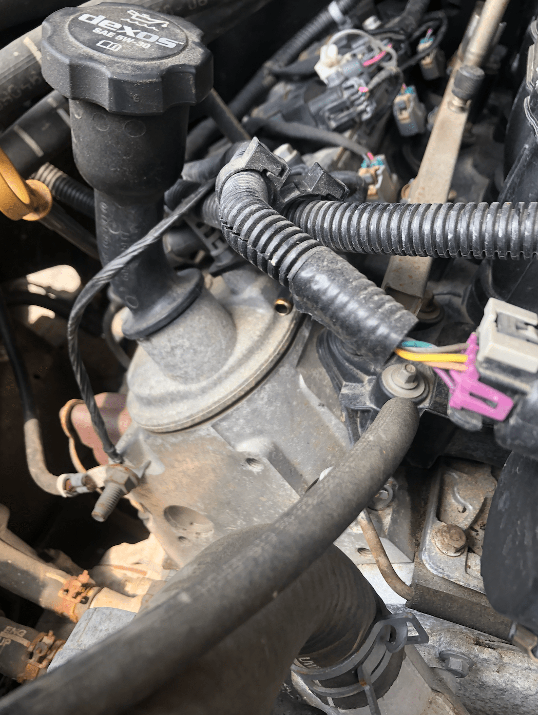
MAF Sensor (Purple connection on the right)
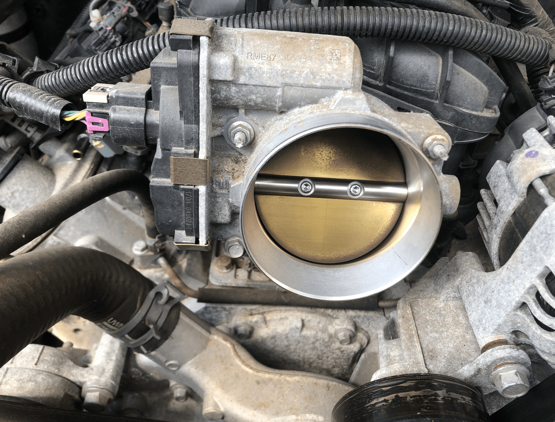
Entry Point of Air Into Engine

Engine Without Intake Tube

Brand New Filter and Airbox
